We are all familiar with the capabilities of a laser cutter, and this is especially true for those of us who enjoy doing things on our own. These kinds of laser cutters tend to be pretty pricey, and in certain cases, the only person who may be authorized to use them is a specialist who will amortize them.
On the other hand, there are methods for building our laser cutter, which will be the topic of discussion in this brand-new tutorial. We can make our own with it, which not only allows us to save a few euros but also allows us to have fun while receiving the satisfaction of knowing that we made it ourselves.
The laser cutter has the capability of cutting or carving markings on various surfaces, which is something that may be extremely useful for some applications. However, it is a device that must be handled with caution because of the danger it poses, and because we are using a tool that may cause issues if we do not respect safety measures, we are required to take necessary precautions to manage it.
Build Laser Cutter in 8 Steps:
Let’s start with the eight stages for making a laser cutter by first going through the overall DIY concept framework and the blueprint. I will go into further detail on the particular manufacturing method and the components included.
Step 1: Motion Control System
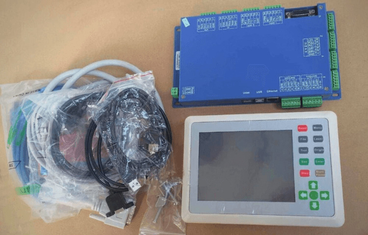
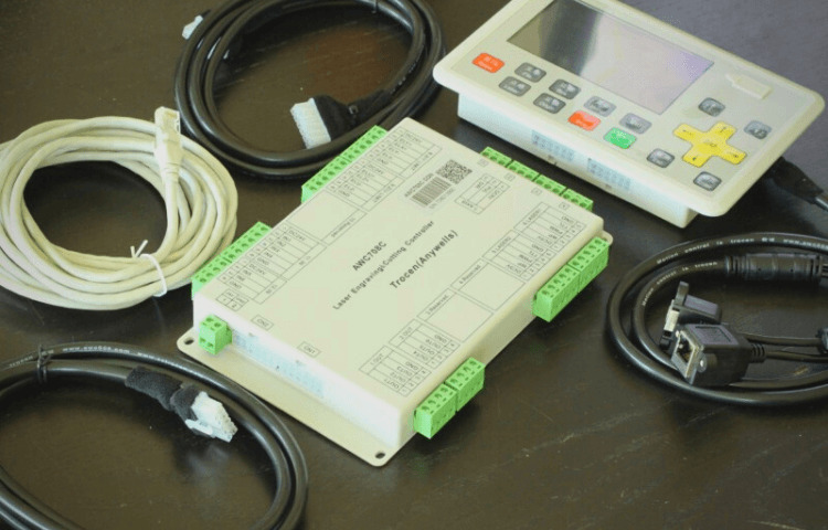
The motion control system is the initial component. The X, Y, Z, and U axes may all be controlled by this motherboard. There is a screen built into the motherboard for user interaction. The operating panel allows users to check the machine’s status, save processing files, and troubleshoot issues; however, adjusting the XYZ axis motor control settings requires a computer connection.
For instance, motor position, laser type selection, and no-load deceleration and acceleration are extremely important and necessary. A 24V DC switching power source is necessary for the control system.
Step 2: Mechanical Design
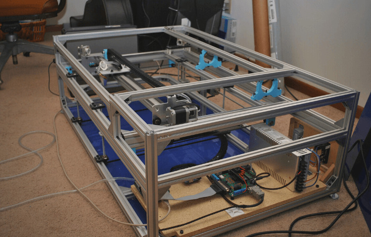
The design of the mechanical system is the second phase in the process. This stage is the primary concern of the laser cutting machine. A logically sound mechanical structure is required to maximize the machine’s potential in terms of its accuracy and functionality.
The first challenge that must be solved at the beginning of the design is to establish the processing itinerary, and the creation of the processing itinerary necessitates the establishment of an initial guiding philosophy. What kind of processing capacity does it require?
Hardware Accessories:
After that, you’ll need to pick up hardware extras like a laser head, an anti, a pair of antis, a synchronous pulley, and so on. Since the precision of the XY axis’s installation dictates the precision of future processing, I opted for a European standard 4040 made of aluminum shape for the main frame.
To prevent deformation while the laser head is in its mid-position, the X-axis beam section is constructed from a 6040 thick aluminum profile and has a broader width than the Y-axis section, which is only 4040 thick.
Parts Processing & Assembly:
The processing and assembly of the components is the next step to take once the design has been finished. This includes processing the X-axis spacer, 3D printing the Y-axis optical axis bracket, assembling the aluminum profile frame, installing the linear guide, and so on.
Accuracy correction is the most important and time-consuming aspect of the process. This procedure calls for several iterations of bug fixing and demands patience.
Test The Mechanical Mechanism Stability:
Check for backlash and modify the stepper motor’s pulse amount based on the discrepancy between the actual distance and the design size by connecting the control system to the computer and running a series of stability tests on the mechanical structure.
Checking the continuity of the strokes and the links between them. The placement accuracy is monitored by sketching the object many times in a row. Of course, the mechanism’s repeatable positioning precision may be measured using a dial indication and a meter.
Step3: Laser Tube Control System
Pick the version with the CO2 laser tube. There are two distinct varieties of laser tubes: the glass tube and the radio frequency tube. The RF tube uses a low voltage of 30V and has great accuracy, a small spot, and long life; however, the price is high.
In comparison, the glass tube has a life of around 1500 hours, the spot is relatively large, and it is powered by high voltage; however, the price is low. Glass tubes are perfectly capable of performing the cutting operation if you plan on working with wood, leather, or acrylic. The majority of laser cutters that are now available on the market use glass tubes.
Because of cost concerns, I decided to use a glass tube with a diameter of 1600 mm and a length of 60 mm. Water cooling is required for the laser tube, and the temperature of the water remains constant.
Laser Tube Installation:
Join the pipe leading to the water heater’s constant temperature outlet. Water enters the laser tube from the top, exits at the top of the negative pole, and then loops via the water circulation safety switch before returning to the bottom.
The laser tube’s positive water input should be pointing downward. The water tank maintains a steady temperature, thereby completing a cycle. When the water pump stops running, a signal is delivered to the control board through the feedback switch, which then switches off the laser tube to prevent it from overheating.
Step 4: Laser Tube Light Guide System Setup
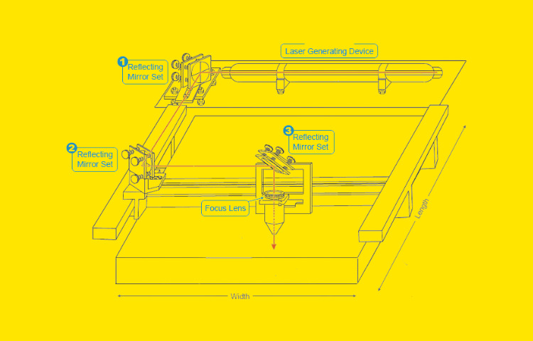
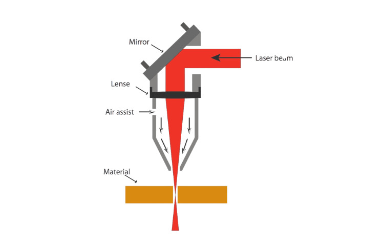
The assembly of the laser tube light guidance system constitutes the fourth component. A mirror reflects the laser light discharged from the laser tube at an angle of ninety degrees to a second mirror, which in turn reflects the light at ninety degrees to a third mirror.
This process is seen in the picture that is located above. Because of refraction, the laser will travel in a downward direction into the focusing lens. The lens will then concentrate the light from the laser into an extremely pinpoint area.
The challenge presented by this system is that the focused spot must always be in the same location, regardless of where the laser top is in the machining process. Another way of putting this is that the optical pathways must coincide while the system moves. If they are not, the laser beam will be deflected, and no light will be produced.
The 1st Surface Optical Path Design:
The procedure of the mirror and the laser being at an angle of 45 degrees to one another makes it difficult to determine the location of the laser point.
After the 45-degree bracket required for auxiliary adjustment has been 3D printed, the textured paper is affixed to the through the hole, and then the laser is activated.
Adjust the bracket’s height, location, and rotation angle so that the light spot is regulated in the middle of the circular hole. Use the spot shooting mode, which has a time of 0.1 seconds and a power of 20%, to avoid penetration.
The 2nd Mirror Optical Path Design:
The exact installation of the second surface mirror bracket is accomplished by measuring with a vernier caliper. The second mirror bracket’s precise installation location and height are achieved through the 3D design of the second surface mirror route (install it to the initial position first).
Change the Angle of Reflection on the first surface Mirror as Necessary:
Moving the Y-axis end closer to the mirror, laser dotting, then moving it farther away, and dotting again, is the procedure for altering the inclination of the first surface mirror. If the near point is higher and the far point is lower, the mirror needs to be rotated upwards, and vice versa.
If the near point is to the left and the far point is to the right, then the mirror needs to be rotated to the left, and vice versa; if the near point is to the right and the far point is to the left, then the mirror needs to be rotated to the right, and vice versa.
Step 5: Blow Exhaust System Setup
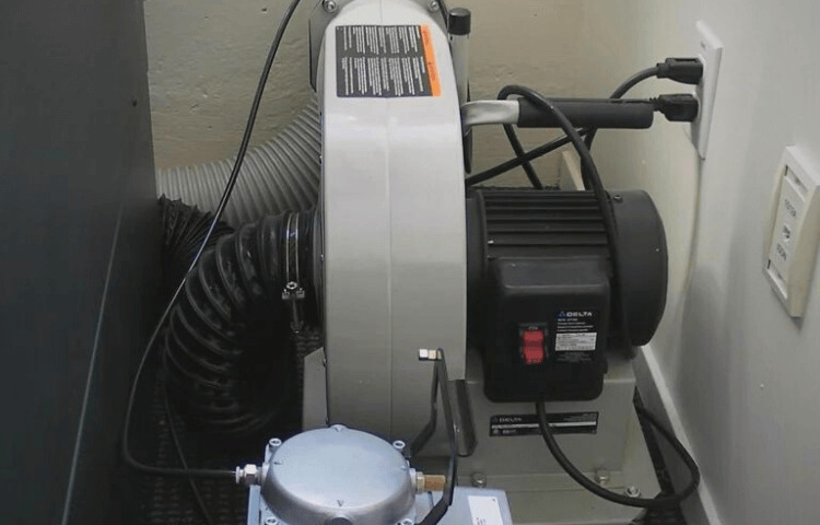
Fifth, air circulation and exhaust systems must be installed. Heavy smoke is produced when a laser is used for cutting; the smoke particles cover the focusing plate, reducing the laser’s effective cutting power. You may fix this by increasing the output of the air pump in front of the focusing plate.
The air compressor air pump is the one I’ve settled on mostly because of the high air pressure it generates and the potential for better cutting efficiency due to the action of the gas being emitted from the pump. The solenoid valve activates the air pump, controlled by an output signal from the main board.
Step 6: Lighting and Focusing Systems Setup
The sixth component is the lighting and focusing system, which uses a power-supply-independent 12V LED light strip and properly incorporates LED illumination for the processing area, the storage space, and the control system. With the addition of the cross laser head placed behind the primary laser, the beam may be focused.
It has a separate 5V power source and switch. The laser’s aiming point is found at the intersection of the two lines. The horizontal laser line determines the board’s depth. If the board isn’t perfectly flat or the focal length is off, the center will be off; therefore, you’ll need to move the focus up and down the Z axis to get it right.
Step 7: Operational Optimization
The seventh component is the optimization of the procedure. A key switch, a USB interface, and a debugging port are all installed on the side of the machine. This is done so that the emergency stop switch can be easily accessed during a stoppage in operation. The emergency stop switch is located on the top of the machine, very close to the work surface.
Because the front is constructed with the primary power switch, air blown and exhaust control switches, LED lighting switches, and laser focus switches, it is possible to do all of the necessary operations with just one panel.
Switch Button Layout:

Cabinet doors are built into the machine’s left and right sides. The cabinet doors on the left side of the machine are used to store the tools utilized by the laser cutter, and the cabinet doors on the right side are used for maintenance and inspection.
At the very bottom of the front is a window that may be used for examination. When a piece of work is dropped, it can be retrieved from the bottom of the container. You may also check to see whether the laser strength is sufficient and whether it has been cut through in time so that you can raise the power during the experiment.
In addition to that, I installed a foot pedal. When you want to start the laser cutter, you must step on the foot pedal to finish the operation. This eliminates the need for the time-consuming button action, which results in a process that is both very quick and very convenient.
Step 8: Test and Debug

Finally, it’s important to debug the laser cutting and engraving processes, test the capabilities of the laser cutting system, and optimize the cutting settings during actual use for the best results.
Conclusion:
The process of laser engraving is as near as current technology comes to being “plug-and-play,” but it is crucial to remember that there is still a learning curve involved. Learn some trade tricks, and be meticulous about testing samples and documenting your favorites. With some mindfulness and attention to detail, you’ll be creating extraordinary results in no time!


